
How therapeutic LINACs evolved
What X-ray tubes and cobalt machines could not do; how microwave technology, bearings, CT, computers, collimators and image guidance changed treatment; and why different accelerator designs still coexist.
Engineering history · Canonical web edition updated 7 November 2026 · Source-review PDF dated 6 November 2026 · Vancouver references · Original schematic drawings and separately credited real photographs
Before the LINAC: what had to change?
For much of the twentieth century, radiation oncology relied on three different methods: kilovoltage X-ray tubes for shallow and moderately deep targets, radioactive sources placed inside or near a tumour (brachytherapy), and external-beam radioactive-source machines such as cobalt-60 teletherapy units. These methods were useful, and some remain essential. The practical problem was how to deliver an adequately penetrating beam to deep tumours, shape it accurately, and reproduce the treatment safely day after day. [1] [2] [3]
An X-ray tube accelerates electrons across a high electrical potential and stops them in a metal target. With conventional kilovoltage therapy, dose falls rapidly with depth and surface or bone dose can be relatively high. That remains an advantage for selected superficial lesions, not a reason to use it for large deep pelvic targets. Brachytherapy is different: a sealed source is brought close to, or into, the treatment site. It offers very steep dose fall-off and has not been superseded by external-beam LINACs, notably in cervical and prostate cancer. [1] [2]
Why cobalt treatments grew longer
Choose how many years a cobalt-60 source has been in service. Its radioactive activity decreases, so the same dose generally needs more beam-on time, assuming otherwise unchanged conditions.
Cobalt-60 made deep teletherapy practical with a compact gamma-ray source. But its activity decreases continuously with a physical half-life of about 5.27 years: beam-on time lengthens as the source ages, and source replacement creates cost, logistics and security obligations. A LINAC generates radiation only when energized and can deliver higher-energy photon beams with finer electronic control. These were important advantages, although LINACs require much more power, maintenance and specialist expertise. [3] [4]

Rob Mieremet / ANEFO, CC BY 4.0 · Original file and licence.

| Technology | What it solved | What remained difficult |
|---|---|---|
| Kilovoltage X-ray therapy | Controllable beam; useful for shallow lesions | Limited penetration for deep targets; skin/bone dose |
| Brachytherapy | Very high local dose and rapid fall-off | Invasive placement, source handling and site-specific applicability |
| Cobalt-60 teletherapy | Compact, penetrating gamma-ray source | Continuous decay; source exchange, security and limited beam modulation |
| Medical LINAC | On-demand MV photons/electrons and electronic beam control | Electrical/RF complexity, scheduled QA and service requirements |
The technologies remain complementary in some indications rather than forming a simple sequence of total replacement.
1953–1970: microwave engineering brings radiation into the hospital
The crucial precondition was high-power microwave engineering. The magnetron and klystron were developed for radio and radar applications, and wartime advances made it possible to deliver intense microwave fields into carefully machined evacuated copper cavities. Electrons injected from an electron gun gain energy as they pass through those cavities. A target converts the electron beam into megavoltage X-rays. [1] [3] [5]
The first hospital medical LINAC treated patients at Hammersmith Hospital in London in 1953. Its accelerating waveguide was metres long, and the machine did not resemble the compact heads used today. The next decades brought rotating, isocentric machines, improved RF efficiency and smaller accelerating structures. A single source could be aimed from different angles while the patient stayed near a fixed point called the . [1] [2] [3] [6]
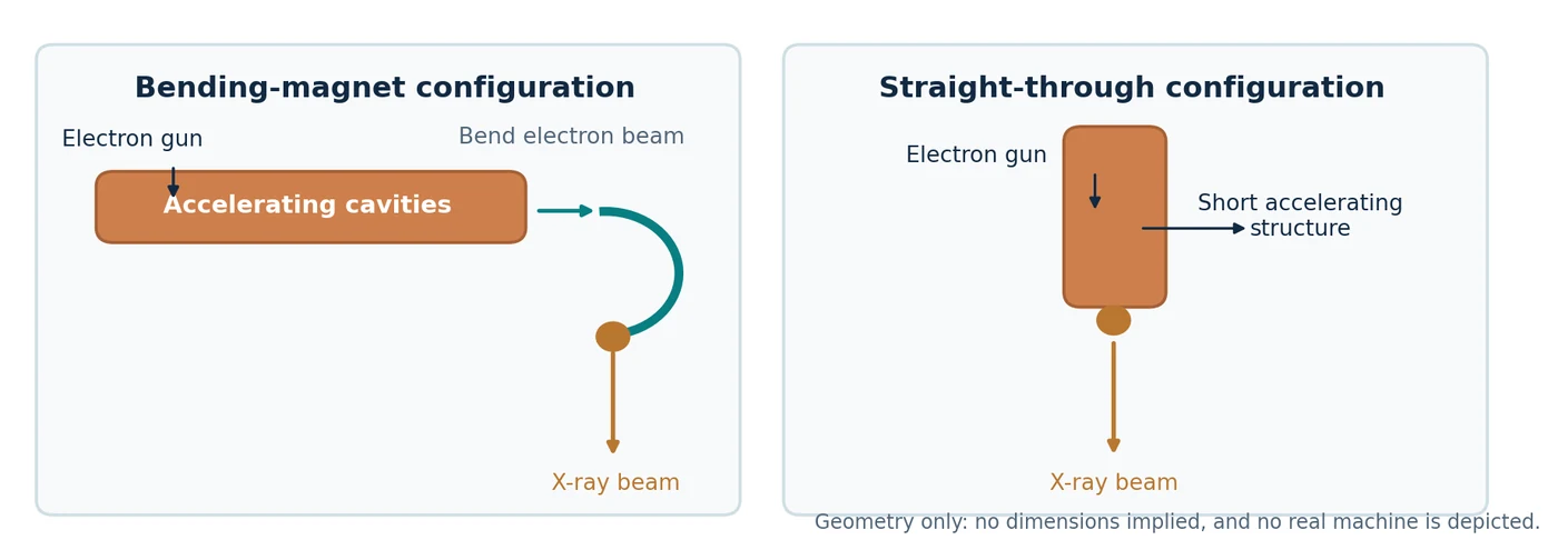
The electron path inside a conventional bending-magnet LINAC
This is a schematic, not a cutaway of a specific manufacturer model. Select a component to see its function.
Microwave cavities transfer energy to electrons travelling along the accelerating structure. This structure can run along the gantry rather than toward the patient.
Illustration shows functional order and orientation; it is not dimensionally accurate and does not represent a 270° electron-optics trajectory.A genuine Clinac cutaway shows why “the accelerator” and “the treatment head” are not the same thing. In many conventional machines the electron gun and accelerating waveguide run along the gantry, away from the downward photon beam direction. A bending magnet turns the electrons toward the X-ray target. Other compact single-energy designs place a short structure in line with the target and need no large electron-bending assembly. The precise configuration depends on the machine. [1] [3]
Guy Lebègue, CC BY-SA 3.0 · Original file and licence.

1970s onward: accurate motion became as important as accurate radiation
A rotating gantry sounds simple: move a heavy arm around a patient. The engineering problem is keeping the radiation axis aimed at the same point throughout rotation. Gravity pulls the head differently at each angle. Bearings have , gears have backlash, frames bend, and heat changes dimensions. A machine can stop its motor to a precise encoder reading and still have a displaced X-ray beam. [1] [7] [8]
Precision bearings carry a heavy rotating assembly while allowing low-friction motion. “Runout” means that a supposedly perfect circle of rotation wobbles slightly; axial runout refers to motion along the bearing axis, radial runout to motion perpendicular to it. Precision bearing sets used in machine tools can reach micrometre-scale runout. For one specific SKF precision bearing arrangement, correctly matched and mounted sets can achieve axial runout of about 2.5 μm. That is 0.0025 mm — not the accuracy of a whole LINAC. [7]
Absolute encoders measure position independently of the motor’s pulse count. One present-day HEIDENHAIN linear encoder specifies an accuracy grade of ±3 μm over a 1,240 mm measuring length, even though its finest electronic measuring step is far smaller. Resolution is not accuracy: displaying more decimal places does not make the machine more accurate. In decimal millimetres, 0.01 mm is 10 μm, 0.001 mm is 1 μm, and 0.0001 mm is one tenth of a micrometre. Final accuracy depends on calibration, mounting, thermal drift, stiffness and independent measurement. [8]
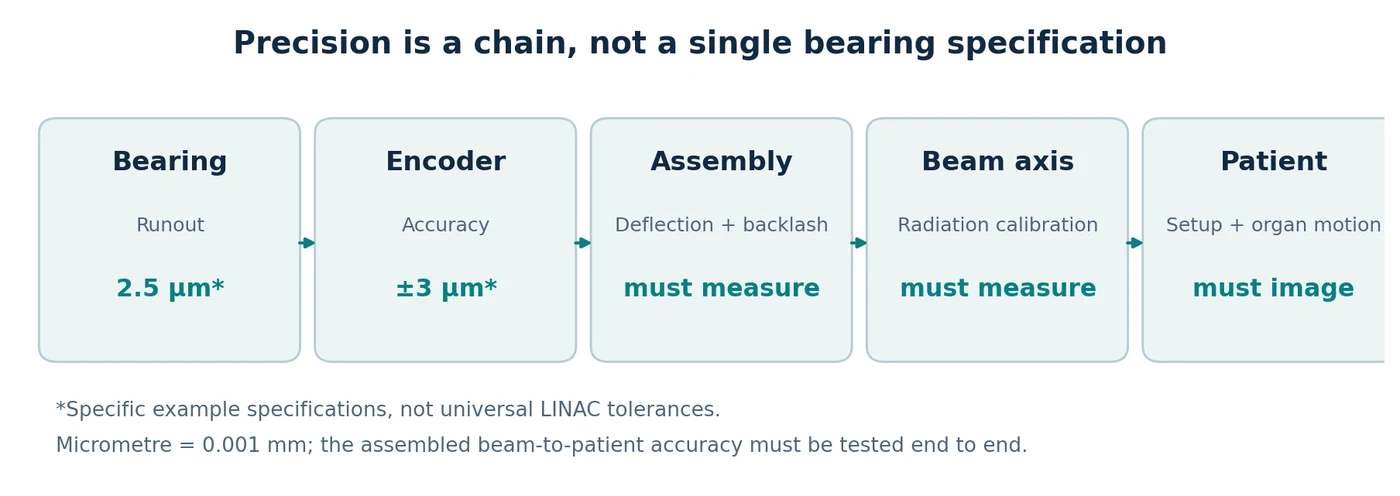
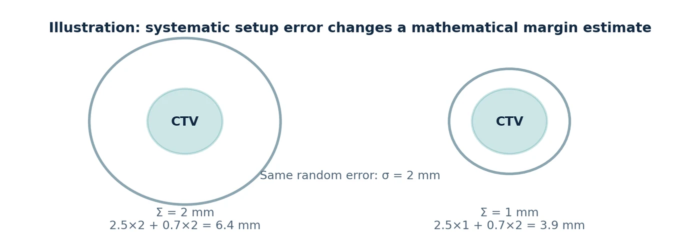
The clinical payoff was not automatic millimetre-for-millimetre reduction of the PTV. The planning target volume is meant to accommodate geometric uncertainties from the entire process: patient setup, organ motion, contouring and delivery. Van Herk and colleagues showed why systematic error matters especially strongly for a course of treatment. A commonly used illustrative margin formula is 2.5Σ + 0.7σ, where Σ describes systematic setup uncertainty and σ random uncertainty, under the original model assumptions. [9]
For example, reducing one modelled systematic error component from 2 mm to 1 mm while holding σ at 2 mm changes that formula from 6.4 mm to 3.9 mm. This is a mathematical illustration, not a recommended clinical margin. A better bearing cannot eliminate respiratory motion, deformation or delineation uncertainty. Smaller margins became realistic only when precise mechanics were combined with better imaging, positioning and motion management. [9] [10] [11]
For non-clinical engineering studies, candidate geometries can be compared before any hardware commitment. A useful matrix would compare, for example, 70, 80 and 100 cm source-to-axis geometry classes for collision workspace, beam divergence and geometric penumbra, expected output implications, structural stiffness and service access. Simulation should then be checked against a physical surrogate: measured displacement, settling time, angular drift, loaded deflection, temperature sensitivity, reassembly repeatability and safe behaviour after power loss. The objective is not to make a mechanism look precise; it is to show that independent measurements agree.
Future design-study experiments
| Observed error | How to expose it | Engineering response to investigate |
|---|---|---|
| Runout or gantry sag | Independent optical/fiducial tracking over a full rotation; compare loaded and unloaded states. | Bearing condition and preload, structural stiffness, guide spacing, mass distribution, alignment and calibration. |
| Backlash / hysteresis | Approach the same angle from clockwise and counter-clockwise directions; repeat after direction changes. | Drive train, gearing, brakes, mechanical locks, direct-position sensing and validated compensation. |
| Couch sag or skew | Track several points on the tabletop while translating/rotating with realistic load. | Support stiffness, guide geometry, bearing spacing, load distribution and position-dependent correction. |
| Thermal drift | Repeat the same geometry from cold start through thermal equilibrium and after long motion sequences. | Thermal management, material choice, sensor placement and temperature-aware calibration. |
| Encoder offset | Compare internal encoder values with an external traceable reference at multiple positions, not just zero. | Recalibration, mounting correction, direct encoders, scale linearity checks and independent verification. |
| Post-service / reassembly shift | Repeat a compact baseline suite immediately after maintenance, component replacement or software changes. | Reference fixtures, reproducible assembly, acceptance testing and documented new baselines before return to use. |
Measure → localize → correct → re-measure
Modern QA frameworks deliberately separate these layers. AAPM TG-142 defines accelerator QA tests and treatment-dependent tolerances; TG-198 provides implementation procedures; and MPPG 8.b emphasizes reference data, routine establishment of machine isocentre, tests matched to clinical use, and repeat testing after maintenance or upgrades. These documents are examples of a QA framework, not a substitute for national requirements, manufacturer procedures or local commissioning. [40] [41] [42]
Mechanical pose
Compare commanded gantry, collimator and couch positions with an independent external reference. Reverse direction to expose backlash and hysteresis; repeat under load and at several gantry angles to reveal sag and flex.
Radiation geometry
Measure where the radiation axis actually passes. Star-shot or Winston–Lutz-type tests answer a different question from an encoder: whether the delivered beam remains coincident with the intended isocentre.
Imaging & patient geometry
Verify that kV, MV or CBCT coordinates agree with the treatment coordinate system and, when clinically relevant, use end-to-end tests that include imaging, positioning, planning and delivery.
Mechanical accuracy is not one number. Resolution is the smallest increment a sensor can display; accuracy is closeness to the true position; repeatability is the ability to return to the same position; and stability is how those properties survive time, load, temperature and maintenance. A machine can therefore report an angle to many decimal places and still have a displaced radiation axis.
Measuring accuracy: the encoder readout is only the beginning
Patient supports: why carbon fibre mattered
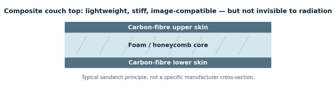
The patient table needs to do several things at once: carry a person, avoid sagging as far as practical, move reproducibly and allow imaging and posterior treatment beams to pass through. Early tables often relied on metal frames and removable open “tennis-racket” inserts. Composite construction made long, relatively stiff and light couch tops with fewer bulky metal obstructions possible. [12]
A common modern design is a sandwich: thin carbon-fibre skins separated by a lightweight foam or honeycomb core. The spacing increases bending stiffness without a solid block of material. But carbon fibre is only relatively radiolucent. It attenuates the beam and can increase skin dose; therefore the treatment planning system must model the couch and immobilization hardware. The AAPM review documents examples of several percent attenuation, depending on energy and beam angle. [12]
1970s–1990s: CT changed what radiotherapy could plan
Before CT, radiation fields were usually designed around skin marks, plain radiographs and a small number of anatomical measurements. CT provided cross-sectional views of the patient, including the tumour and structures that should be spared. The first clinical CT scan was obtained in 1971; Hounsfield published the method in 1973. Three-dimensional planning and CT simulation developed over the following decades rather than appearing overnight. [13] [14]
Computer models could now calculate the path of each beam through different tissue densities and display the dose in three dimensions. Digitally reconstructed radiographs (DRRs) gave an image with which to compare treatment-room images. CT did not make anatomy perfectly visible, and later MRI and PET integration remained important. But it changed planning from drawing a field on a body outline to designing dose around a three-dimensional target. [13] [14] [15]
Philip Cosson, public domain · Original file and licence.

From lead blocks to computer-controlled leaves
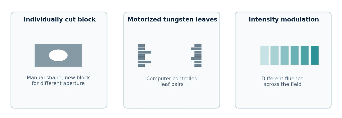
For decades, technicians shaped fields using custom metal shielding blocks. This was effective but labour-intensive: a different opening meant a different block, mounted on a tray. Motorized jaws provided rectangular fields, wedges modified beam intensity, and compensators changed fluence with depth or position. These were practical precursors of modern modulation, not primitive ideas to be dismissed. [14] [15]
The (MLC) replaced many custom blocks with rows of narrow tungsten leaves. Each leaf or leaf pair moves into the radiation field under computer control. The machine can make an irregular opening without a new manufactured block, or change the opening repeatedly during one fraction. Ideas appeared earlier, but commercially useful MLC systems emerged in the 1980s–1990s as motors, position feedback and control computers improved. The first commercial MLC realized by Scanditronix was reported in 1984. [14] [16]
How fields were shaped
Select a field-shaping method. The yellow area shows the opening at the treatment head; the teal outline is an irregular target projection. This is geometry, not a dose calculation.
A multileaf collimator forms different apertures under computer control; it can modulate the beam without replacing heavy custom blocks.
Not a patient dose or penumbra simulation; leaf-tip leakage and scatter are not represented.The limitation is mechanical and dosimetric. More, thinner leaves improve geometric shaping but add motors, sensors, mass and maintenance points. Rounded leaf tips, interleaf leakage and motion errors need accurate modelling. An MLC is not a perfect opaque stencil. [16]
Jejecam, CC BY-SA 3.0 · Original file and licence.

Inverse planning: the decisive software change
Traditional forward planning asks: “If these beams are used, what dose will they produce?” reverses the problem: “What beam intensities will best satisfy these target and organ-at-risk objectives?” Anders Brahme and colleagues formalized influential approaches in the 1980s. Optimization algorithms then converted desired dose distributions into patterns that the MLC could deliver. [15] [16] [17]
The idea required computers capable of dose calculation and optimization, electronically controlled leaves, and reliable machine communication. Commercial IMRT reached patients in the 1990s, initially through specialized systems such as NOMOS MIMiC/Peacock and later on conventional LINACs. Continuous gantry motion with changing MLC leaves and dose rate led to volumetric modulated arc therapy (VMAT), typically reducing delivery time compared with many fixed IMRT fields for suitable cases. The planner must still check whether the plan is deliverable and safe. [15] [16] [17]
1990s–2000s: the machine learns to see where the patient is
A planning CT is an image taken on a different day. The patient can be shifted, the bladder can fill differently and a lung tumour can move with breathing. Image-guided radiotherapy (IGRT) adds measurements made on or near the treatment machine and compares them with the planning reference. [10] [18] [19]
Why kilovoltage and megavoltage imaging are different
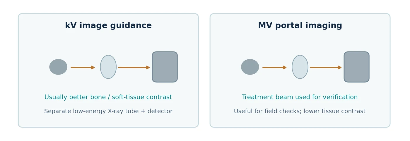
A kilovoltage (kV) imaging system usually uses a separate diagnostic-energy X-ray tube and flat-panel detector. It often gives better contrast between bone and surrounding tissue and can acquire projections for cone-beam CT. A megavoltage (MV) portal image uses the high-energy treatment beam and an electronic portal imaging device (EPID) on the opposite side. It is excellent for verifying treatment-field geometry, but its subject contrast is generally poorer because high-energy photons interact differently with tissue. [10] [18] [19]
Two real published comparisons: a prostate study provides side-by-side anteroposterior and lateral MV portal and kV images of implanted fiducial markers in clinical patients; a review illustrates MV portal alignment using skull and head-and-neck bony anatomy compared against DRRs. These are actual published examples and are linked directly in the online article. They show what each method detects, rather than invented “before and after” pictures. [10] [19]
The next step was rotating the imaging tube and detector to reconstruct a three-dimensional image. Jaffray and colleagues demonstrated flat-panel cone-beam CT for image guidance in 2002. On-board CBCT helps detect changes in the location of the tumour and organs, but has its own limits in scatter, image artefacts and soft-tissue contrast. [10] [18]
2000s–2020s: movement introduces a fourth dimension
A tumour does not necessarily remain at one point throughout a fraction. Four-dimensional CT () groups images by respiratory phase to show movement over a breathing cycle. It enables internal target volumes, gating windows and more informed motion management. Early practical methods were described around 2004; respiratory tracking, breath-hold methods and surface monitoring then became progressively integrated into clinical equipment. [11] [20]
The trade-off is important: imaging a moving target does not make it stationary. A 4DCT reflects breathing during that scan, while breathing may vary during treatment. Gating pauses irradiation outside a chosen window; tracking moves the beam or adjusts delivery; breath-hold asks the patient to adopt a repeatable respiratory position. Each works only when its correlation with the internal target has been validated. [11] [20]
Different geometries for different clinical problems
The conventional rotating C-arm
The familiar C-arm keeps a relatively large accelerator and MLC rotating around a fixed isocentre. It is a broadly useful architecture for conformal treatment, fixed-field IMRT, VMAT, electrons on equipped systems and many types of SBRT. Its strengths are generality and a mature maintenance ecosystem; its limits include the large moving mass, rotational radius and the finite range of collision-free noncoplanar directions. [1] [21] [22]
Michael Goodyear, CC BY-SA 4.0 · Original file and licence.

Chris Olszewski, CC BY-SA 4.0 · Original file and licence.

TomoTherapy: why a CT-scanner-like ring?
TomoTherapy places a LINAC on a ring and advances the patient couch through the bore while the source rotates, delivering narrow fan-beam radiation in a spiral. This suited complex and long targets and combined treatment with megavoltage CT imaging. The ring geometry reduces some possibilities for strongly noncoplanar beam directions and its narrow fan beam can make some plans slower than modern VMAT; delivery time depends strongly on target length and planning settings. Modern descendants include the commercial Radixact system. [16] [21] [23]
ASL Reggio Emilia, CC BY-SA 3.0 · Original file and licence.

CyberKnife: move the source instead of the patient
CyberKnife attaches a compact LINAC to an industrial robotic arm, providing many noncoplanar beam directions. It grew especially useful for stereotactic radiosurgery, body stereotactic radiotherapy and image-guided target tracking. The price is more moving joints, a specialized imaging and control system, and complex robot/path calibration. It is not simply a small version of a conventional C-arm. [21] [23]
Minaforpresident, CC BY-SA 3.0 · Original file and licence.

Vero4DRT: what exactly is a gimbal?
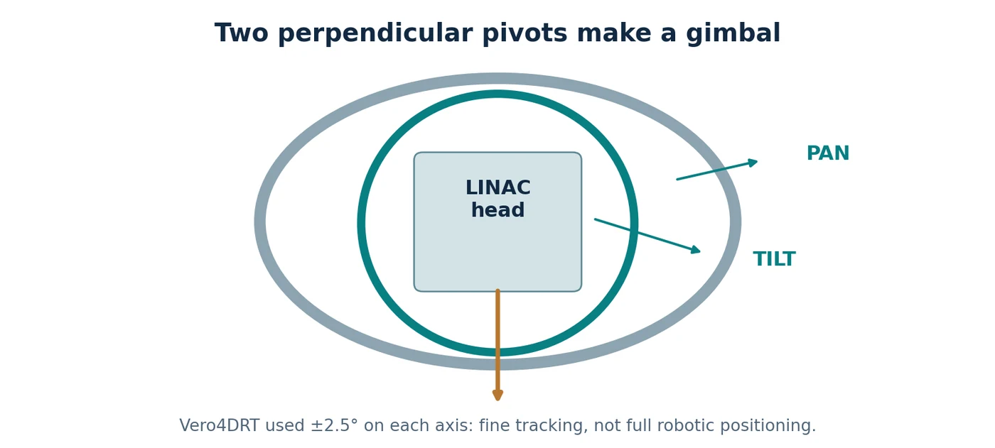
A is a joint system with two perpendicular rotational axes: a cradle can pan left and right and tilt up and down independently. Gimbals were used in maritime compasses and nautical clocks long before radiotherapy: two hinged rings helped an instrument remain roughly level as the ship rolled. This is sometimes called a Cardanic suspension, although examples predate Girolamo Cardano. Cameras and telescopes later used related mechanisms. [24] [25] [26]
Vero4DRT used a compact C-band LINAC on an O-ring and a two-axis gimballed X-ray head. Each axis could rotate approximately ±2.5°, enough to shift the radiation beam by several centimetres at isocentre for fine real-time tracking. Larger angular access still came from the gantry/O-ring. Two orthogonal kV tubes and detectors observed internal anatomy; the gimbal then adjusted the MV radiation direction. A gimbal is therefore fine beam steering, not a six-axis robot. [24] [25]
MRI-LINACs and online adaptation
The MR-LINAC brought another kind of information to the treatment machine: high-quality soft-tissue imaging while the patient is positioned for irradiation. This meant developing accelerators compatible with strong magnetic fields, new shielding and imaging reconstruction, and new workflows. First patients were treated on a 1.5 T MR-LINAC in Utrecht in 2017. The equipment is expensive and clinically useful for selected targets that are poorly seen with ordinary kV imaging. [27]
CBCT-based online adaptive treatment took a related but different route. Systems such as Ethos use the day’s images to update contours, calculate or select a plan, check it and deliver it while the patient stays on the couch. Better GPUs and automated contouring made this workflow practical, but adaptation adds review and QA work instead of magically removing the clinician. Auto-contouring of organs is increasingly useful; defining malignant extent remains a separate clinical judgment. [28] [29]
A practical comparison of recognisable machine families
These systems are not ranked by purchase price because comparable public, installed-and-supported quotations are generally unavailable. Clinical treatment time also varies with target size, fractionation, modality and planning. The table instead compares the engineering choices that determine strengths and trade-offs. Historical systems are marked clearly. [21] [22] [23] [27] [30] [31] [32]
| Machine family | Geometry / imaging | Main strength | Principal limitation / burden |
|---|---|---|---|
| Conventional C-arm: TrueBeam, Versa HD | Rotating C-arm; kV CBCT and MV portal imaging | Most versatile general-purpose platform | Large gantry, shielding and service infrastructure |
| Halcyon / Ethos | Compact ring; integrated kV CBCT; Ethos adaptation | Efficient standardised workflow; daily anatomy-informed planning | Restricted noncoplanar access; adaptation adds staff time |
| TomoTherapy / Radixact | Helical ring; MVCT | Very long or complex target volumes | Narrow fan-beam geometry; less noncoplanar flexibility |
| CyberKnife S7 | Six-axis robot; stereoscopic imaging / tracking | Many noncoplanar beam directions; moving-target stereotaxy | Specialised robotics, imaging and long-term maintenance |
| Vero4DRT (historic) | O-ring plus pan/tilt gimbal; paired kV imagers | Fine beam tracking plus noncoplanar access | Complex custom architecture; not a current mainstream product |
| Elekta Unity MR-LINAC | Ring LINAC coupled to 1.5 T MRI | Soft-tissue visibility and on-table adaptation | Magnet integration, workflow duration and infrastructure |
| ZAP-X | Dedicated self-shielded intracranial radiosurgery | Compact dedicated brain SRS footprint | Not a multipurpose whole-body workhorse |
| Siddharth-II | Compact ring with beam stopper; option-dependent MLC/IGRT | Marketed toward accessible general-purpose radiotherapy | Published performance and service footprint vary by model/region |
A qualitative comparison of capabilities, not a numerical performance ranking or a claim of equivalent indications.
Access to radiotherapy: projects and marketed responses
Clinical access depends on more than the machine: staff, simulation, treatment planning, shielding, electrical reliability, spare parts and service contracts matter. Several responses are visible in the literature. The Indian-manufactured Siddharth-II is a marketed medical LINAC, with US FDA 510(k) clearance records. CERN’s STELLA project, by contrast, has published work on a modular, serviceable system specification; it is a development and access initiative, not a finished commercial LINAC. [31] [33]
The Australian Nano-X project has investigated a fixed beam combined with patient rotation, in part to simplify the mechanical structure. Its published 2023 work describes a prototype and imaging feasibility programme. The associated clinical trial record was updated in May 2026 as withdrawn because funding was unavailable. This does not by itself establish that the underlying engineering concept failed, but it is important evidence about development maturity. [34] [35]
Patents: interesting mechanisms that did not become familiar products
A patent records a proposed technical solution and the claims its inventors sought to protect. It does not prove that a complete medical device was built, qualified or commercially sold. Three instructive examples appeared after conventional C-arms and robotic systems were already established. The engineering challenges described below are plausible obstacles, not documented explanations for each company’s product decisions. [36] [37] [38]
| Proposal / earliest priority | Problem it addressed | Mechanical idea | Why integration would be demanding |
|---|---|---|---|
| Siemens, 2009: linear guides with rotating head | Fixed-radius gantry limits source positioning | Orthogonal straight rails plus one or more head rotations | Large moving frame, patient clearance, cable routing, multi-axis calibration |
| Accuray, 2011: inward-extending ring head | Fixed source distance limits geometry | Radial translation of entire head from a ring | Heavy moving payload, deflection at extension, collision and calibration |
| Accuray, 2010s: head that slides and pivots on a rotating beam | Broaden noncoplanar beam access | Head translation along beam plus two pivot axes and ring motion | Many coupled moving axes and a complex shielding/clearance envelope |
Representative disclosed concepts. No commercial product matching these claimed combinations was established in the sources reviewed.
Their patent figures are worth studying precisely because they force the reader to ask where the heavy mass moves, how much additional travel is needed, and what the patient and couch obstruct. The diagrams and full claim sets can be inspected in the cited original patent records. A legal status such as “expired for fees” concerns a particular patent and jurisdiction, not all related intellectual property. [36] [37] [38]
What ultimately drove progress?
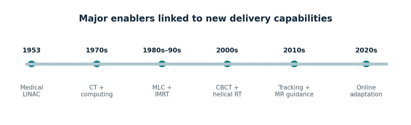
The first decisive step was generating penetrating radiation electronically. The second was making the source move around a stable reference point. CT then provided three-dimensional anatomy to plan against. Motorized collimators made complex fields repeatable, while computing made inverse planning feasible. On-board imaging linked the plan to the patient in the treatment room. Finally, fast imaging, more powerful computation and reliable motion control made respiratory tracking and online adaptation possible. [1] [10] [11] [13] [14] [15] [16] [17] [18] [19] [20] [24] [25] [27] [28] [29]
No single bearing, patent or algorithm accounts for the gain. The history of therapeutic LINACs is best understood as the gradual removal of the largest uncertainty at each stage: energy, pointing, anatomy, beam shape, patient position and internal motion. New equipment succeeds when several of those problems are solved together, reliably enough to be used every day. [1] [9] [10] [20]
References
- Thwaites DI, Tuohy JB. Back to the future: the history and development of the clinical linear accelerator. Phys Med Biol. 2006;51:R343–R362. Source. ↑
- British Institute of Radiology. Radiotherapy in the 1950s. Historical archive. Source. ↑
- Almond P, Orton C. Early developments in teletherapy machines. Med Phys. 2013;40:499. Source. ↑
- Centers for Disease Control and Prevention. Cobalt-60. 2024. Source. ↑
- AAPM Virtual Museum. External beam radiotherapy. Online historical exhibit. Source. ↑
- Bewley DK. The 8 MeV linear accelerator at the MRC Cyclotron Unit, Hammersmith Hospital, London. Br J Radiol. 1985;58:213–217. Source. ↑
- SKF. Bearing data: precision axial bearing tolerances and running accuracy. Manufacturer technical data. Source. ↑
- HEIDENHAIN. LC 495F sealed linear encoder: technical data. Source. ↑
- van Herk M, Remeijer P, Rasch C, Lebesque JV. The probability of correct target dosage: dose-population histograms for deriving treatment margins. Int J Radiat Oncol Biol Phys. 2000;47:1121–1135. Source. ↑
- Goyal S, et al. Image guidance in radiation therapy: techniques and applications. Radiol Res Pract. 2014;2014:705604. Source. ↑
- Keall PJ, et al. Acquiring 4D thoracic CT using a multislice helical method. Phys Med Biol. 2004;49:2053–2067. Source. ↑
- Olch AJ, Gerig L, Li H, et al. Dosimetric effects caused by couch tops and immobilization devices: AAPM TG-176. Med Phys. 2014;41:061501. Source. ↑
- Hounsfield GN. Computerized transverse axial scanning (tomography): Part 1. Description of system. Br J Radiol. 1973;46:1016–1022. Source. ↑
- Balter JM, et al. Anniversary paper: novel technologies and medical physicists in radiation oncology. Med Phys. 2008;35. Source. ↑
- AAPM Virtual Museum. Treatment planning and development of modern external beam radiotherapy. Online historical exhibit. Source. ↑
- Intensity-modulated radiation therapy: a review with a physics perspective. Open-access review. 2018. Source. ↑
- Brahme A. Optimization of stationary and moving beam radiation therapy techniques. Radiother Oncol. 1988;12:129–140. Source. ↑
- Jaffray DA, Siewerdsen JH, Wong JW, Martinez AA. Flat-panel cone-beam CT for image-guided radiation therapy. Int J Radiat Oncol Biol Phys. 2002;53:1337–1349. Source. ↑
- Electronic portal imaging versus kilovoltage imaging in fiducial-marker IGRT for prostate cancer. Br J Radiol. 2012. Source. ↑
- Keall PJ, et al. AAPM TG-324 / Report 91.b: management of respiratory motion in radiation oncology. Med Phys. 2026. Source. ↑
- Accuray. CyberKnife and Radixact treatment systems. Company product overview; accessed 2026. Source. ↑
- Elekta. Radiation therapy systems, including Unity, Versa HD, and Harmony. Product catalogue; accessed 2026. Source. ↑
- FDA. Device listing: CyberKnife S7, Radixact, Stellar and related systems, 2026. Source. ↑
- Feasibility evaluation of three-dimensional unicursal irradiation with Vero4DRT. Open access. 2013. Source. ↑
- Rostamzadeh A, et al. Markerless dynamic tumour tracking using the diaphragm on Vero4DRT. J Appl Clin Med Phys. 2024. Source. ↑
- Museo Galileo. Gimbals: historical use in maritime compasses and clocks. Historical instrument catalogue. Source. ↑
- Raaymakers BW, et al. First patients treated with a 1.5 T MRI-Linac. Phys Med Biol. 2017;62:L41–L50. Source. ↑
- Adaptive radiotherapy: next-generation radiotherapy. Cancers. 2024;16:1206. Source. ↑
- Matoska T, et al. Review of deep-learning autosegmentation for clinical target volume. Adv Radiat Oncol. 2024;9:101470. Source. ↑
- FDA. ZAP-X radiosurgery system 510(k) K250392, 2025. Source. ↑
- FDA. Siddharth-II/IMPACT 510(k) K222762, 2023. Source. ↑
- ViewRay Systems Inc. Investors and MRIdian product information. Accessed 2026. Source. ↑
- CERN. STELLA project concludes an 18-month hardware and software design phase. Source. ↑
- Nano X image guidance: protocol for CBCT with patient rotation. Pilot Feasibility Stud. 2023. Source. ↑
- ClinicalTrials.gov. Nano-X Image Guidance: CBCT With Gravity-induced Motion, NCT04488224. Updated 2026 May 19; status Withdrawn. Source. ↑
- Siemens. Linear kinematics system with rotatable treatment head. US patent 8488739 B2, published 2013. Source. ↑
- Accuray. Ring gantry with dynamically controllable inward extension of treatment head. US patent 8536547 B2, published 2013. Source. ↑
- Accuray. Rotatable gantry radiation treatment system. US patent 9700740 B2, published 2017. Source. ↑
- National Cancer Institute. TomoTherapy treatment image; NCI public-domain media via Wikimedia Commons. Source. ↑
- Klein EE, Hanley J, Bayouth J, et al. Task Group 142 report: Quality assurance of medical accelerators. Med Phys. 2009;36:4197–4212. AAPM report. ↑
- Hanley J, Dresser S, Simon WE, et al. AAPM Task Group 198: An implementation guide for TG-142 quality assurance of medical accelerators. Med Phys. 2021. AAPM report. ↑
- AAPM Medical Physics Practice Guideline 8.b: Linear accelerator performance tests. 2023. AAPM guideline. ↑
